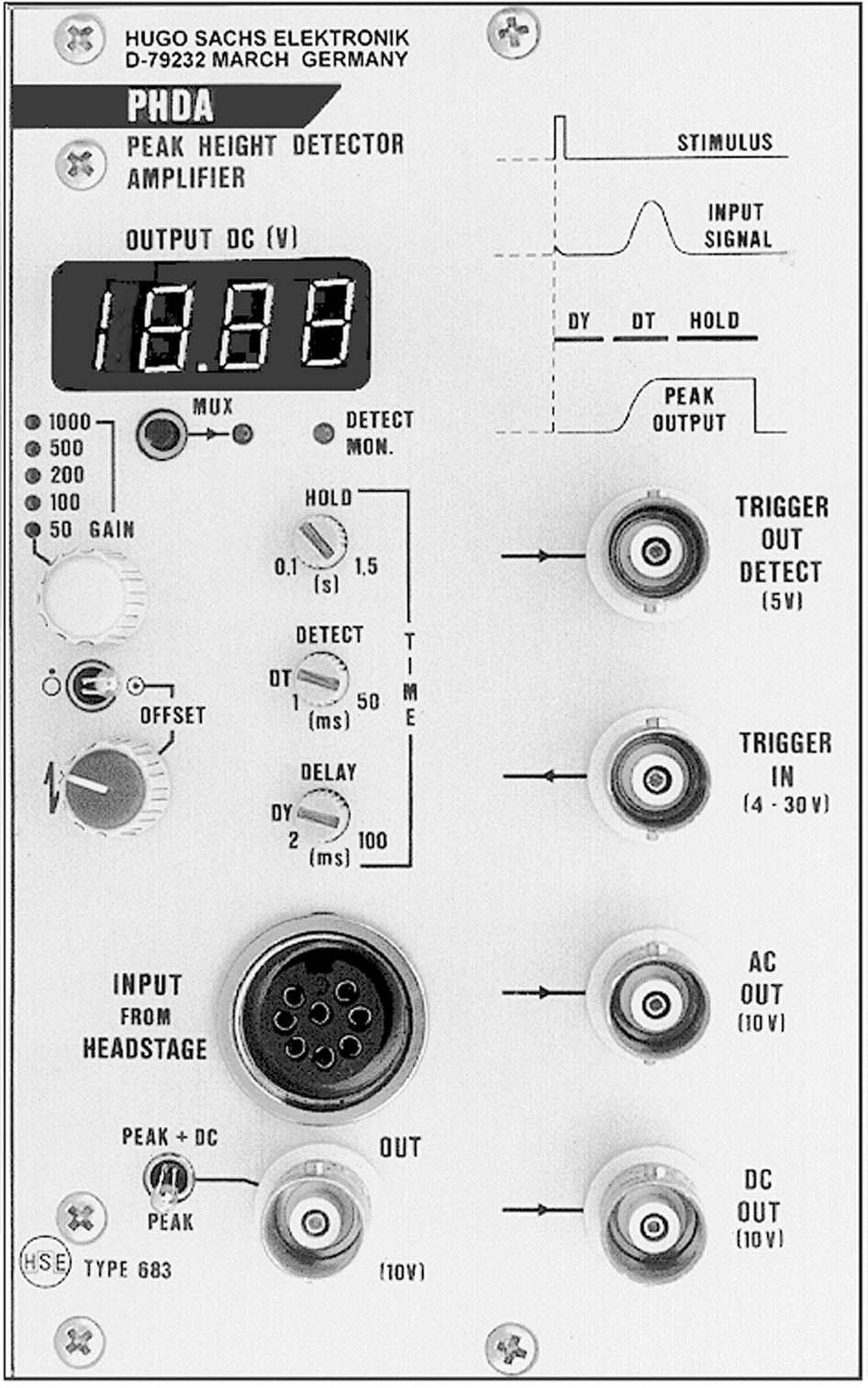
PLUGSYS Peak Height Detector Amplifier Module (PHDA)
Special amplifier for recording extracellular signals from isolated sympathetic ganglia or whole nerve bundles. Works in combination with the Marsh Chamber.
The Peak Height Detector Amplifier Module (PHDA) is used in conjunction with the ganglion chamber according to MARSH for measuring extracellular potentials of isolated sympathetic ganglia and whole nerve bundles of the rat.
The Peak Height Detector incorporates a variable gain, low-noise differential amplifier and a spike amplitude evaluator. This enables simultaneous monitoring of low amplitude D.C. signals and the amplitude of a selected portion of an evoked potential. The input circuit of this amplifier includes a headstage which is placed near the ganglion chamber. The peak height detector output, which can be displayed on a chart recorder or connected to a computer Data Acquisition System, provides a single continuous record of changes in potential difference (membrane potential) and evoked potential amplitude or separate traces of the same two components, enabling high gain recording of low amplitude changes in membrane potential. An amplified signal output allows oscilloscope monitoring of the evoked potential and adjustment of the detection region for the peak detector.
| Specifications | 73-1743 |
|---|---|
| AC Out | Output of AC voltage, BNC connector 10 V, 10 mA; output used to connect oscilloscope |
| Accessories | 2x BNC-BNC cable; 3x BNC-banana cable; 2x BNC-banana adapter; operating instructions |
| Connector | DIN 41612, 96-pin VG |
| DC Out | Output of DC voltage to chart recorder or oscilloscope; DC voltage shown in display; BNC connector |
| Delay | During time peak height detector is out of action, peak height detector is enabled for detect duration; delay time can be set in range from 2 to 100 msec |
| Detect | Time is on-time for detecting max. of input signal; detect time can be set in range from 1 to 50 msec |
| Dimensions (H x W x D) | 5.1 x 3.2 x 8.7 in (128.7 x 80.8 x 220 mm) |
| Frequency Range | AC 1.5 Hz to 40 kHz (-3 dB)
DC 0 to 0.2 Hz (-3 dB) |
| Gain | Switchable x50/100/200/500/1000 (including Headstage Gain 10) |
| Hold | Hold time is duration of holding amplitude of peak in peak memory; time can be set from 0.1 to 1.5 seconds. |
| Input from Headstage: Common Mode Rejection Ratio | >120 dB |
| Input from Headstage: Gain | 10 (only for headstage) |
| Input from Headstage: Headstage | Differential Input |
| Input from Headstage: Input Capacity | 20 pF |
| Input from Headstage: Input Impedance | >1012Ω |
| Input from Headstage: Max. Differential Voltage | >0.2 V |
| Input from Headstage: Noise | 40 μVpp |
| Input from Headstage: Overshoot Protection | 15 V constant, 100 V non-repetitive peak |
| Offset | Fine adjustment with 10-turn potentiometer, can be switched off |
| Out | Signal output used to connect up chart recorder or oscilloscope; it is possible to switch voltage peak height or peak height and additional DC voltage to BNC connector with switch PEAK/PEAK+DC. 10 V, 10 mA BNC connector |
| PLUGSYS Width* | 4 slot units |
| Power Supply | 5 V/0.7 A through connector from PLUGSYS bus system |
| Signal Output MUX | After pressing MUX key, one of analog voltages (depending on switch PEAK/PEAK+DC) is switched to system bus line AM (analog multimeter), which can be switched to |
| Signal Output MUX 2 | Digital Display Module (DM) or Digital Voltmeter Module (DVM). Function is self-maintained; module previously selected is switched off. |
| Trigger IN: BNC Connector | 4 to 30 V |
| Trigger IN: Input Resistance | 5 kΩ |
| Trigger Out Detect | Monitor output, TTL level, to control detect time with oscilloscope, BNC connector |
| Weight (Metric) | 500 g |

